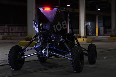
Axial load bearing suspension


After two years of experience in Baja SAE, I realized the previous rear suspension design lacked rooms for further improvement and wanted to take the performance of the future vehicles to new levels in reliability, weight reduction and handling and boost the team’s performance in the competitions.


I designed the axial load bearing rear suspension to eliminate the heavy and unreliable constant velocity joints, steel half shafts, and lower control arms. By eliminating the lower control arms and integrate their abilities into the aluminum half shafts and universal joints, I designed the rear suspension geometry to achieve both no camber gain through travel and zero half shafts plunge. The gearbox and half shafts have to able to take axial loads.


The travel of the rear suspension had to match the front to maintain vehicle’s handling in corners. The universal joints were selected to ensure the reliability of the vehicle and the angle of suspension travel was satisfied. The rear section of the frame and shocks mounts were developed through three differential equations and solved by Gaussian elimination and CAD with iterations in MATLAB.
